Dip-spinning is a bulk coating process used for coating large quantities of parts. The basket or drum, with a diameter of 400–900 mm, is the primary tool. Parts are loaded into the basket, with the fill level depending on the bulk density of the parts. Depending on the dip-spin parameters and coating settings, an average coating thickness of 3–6 μm per layer can be achieved.
For parts with complex geometries (e.g., internal threads, small components, undercuts), it is advisable to rotate the basket to ensure full surface coverage. The same applies for centrifuging excess coating material after coverage. A tilt angle of ≥ 75° at 5–20 rpm allows better drainage of excess coating. This can be combined with a pre-spin before tilting.
Next, the basket is immersed into the coating bath. Slow rotation of the basket improves coverage by removing bubbles and adjusting contact surfaces.

After dipping, the basket is lifted and rapidly spun or centrifuged so that coated parts move to the outer wall. Centrifugal force causes excess coating to drain back into the bath. Parts are then dried in the oven. For better curing and reduced sticking, parts should be distributed as far apart as possible on the conveyor or tray.
The dip-spin process is influenced by parameters such as immersion time, spin speed, spin duration, basket load, and coating viscosity. Additional factors include tilting or changing rotation direction to improve quality.
Recommended parameters: The basket must be immersed for at least 30 seconds. Low rotation (10–20 rpm) with oscillation improves coverage and removes trapped bubbles.
An important parameter is centrifugal force (F), dependent on rotational speed and basket diameter. To ensure comparable results with different basket sizes, the centrifugal force should be equivalent.
The centrifugal force is calculated as: \( F = m \omega^2 d / 2 \)
m = mass of a drop of coating (nearly constant)
d = diameter
\(\omega\) = angular velocity (\(\omega = 2\pi n/t\))
n/t = revolutions per unit time (e.g. rpm/60)
Formula for different basket sizes: \( F = m \left(2\pi \frac{n_1}{60}\right)^2 \frac{d_1}{2} = m \left(2\pi \frac{n_2}{60}\right)^2 \frac{d_2}{2} \Rightarrow n_2 = n_1 \sqrt{d_1/d_2} \)
Basket diameter (d1) = 900 mm, rotation speed (n1) = 219 rpm
Convert to basket diameter (d2) = 500 mm, rotation speed (n2)?
n2 = 219 rpm × √(900 mm / 500 mm) = 294 rpm
To achieve comparable coating results, smaller baskets require higher rotational speed.
| Basket Diameter [mm] | Speed [rpm] |
|---|---|
| 300 | 380 |
| 400 | 329 |
| 500 | 294 |
| 600 | 268 |
| 700 | 248 |
| 800 | 232 |
| 900 | 219 |
| 1000 | 208 |
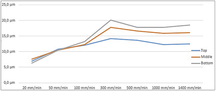
Coating thickness depends on spin speed and basket diameter: higher speed and larger diameter result in thinner layers at the same viscosity.

Spin duration is typically 10–20 seconds per direction, often repeated for complex part geometries.
Basket construction and geometry also influence the process. Closed or double-walled baskets require adjusted spinning parameters.
The part quantity and spin acceleration affect the coating flow (see Figure 12). Ideal flow is seen in examples a) and b). Overloaded or slow acceleration leads to uneven coating and possible sticking, as shown in examples c) and d.
Coating weight is influenced by viscosity. Lower viscosity results in less coating adherence. Adjust viscosity according to part geometry and system design. For solvent-based basecoats, a starting viscosity of 40–42 s is recommended.
A sample coating is applied to verify coating weight and confirm requirements. If requirements are not met, adjust spin speed, spin duration, viscosity, and basket load.
As noted in Section 3.3, viscosity is influenced by temperature, solvent evaporation, and solids content. Maintain constant coating temperature for consistent quality. Temperature can be affected by day/night changes, oven radiation, warm parts, and climate variations.
Establish and maintain a defined processing viscosity window (±2 s). The coating system often consists of multiple layers. Parts are transported between basket and oven; minimize handling to prevent coating damage.
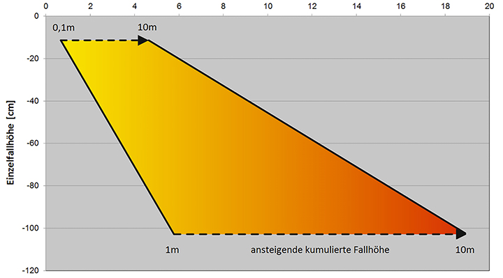
Parts should be gently unloaded onto the pre-curing conveyor or tray to prevent damage. Larger parts or greater drop height increase damage. Rubber/plastic surfaces and reduced drop height help mitigate damage. Vibrations from feeders or post-coating drops can also affect quality.
For re-coated parts, temperature must be ≤30 °C but above dew point. Basecoats and topcoats require separate baskets and immersion tanks. Incorrect thinner can damage the coating.
Regular cleaning of coating baskets is mandatory to remove built-up dried coating. Methods include wet-chemical, thermal, mechanical, or laser cleaning.

Comments (0)
No comments yet.
Do you have constructive feedback?
Please log in to leave a comment.