7. IN-PROCESS INSPECTIONS
In order to achieve the best possible coating system quality, there are a number of in-process inspections that must be performed before, during and after the coating application process.
| Coating Material | Part | Environment | |
|---|---|---|---|
| Pre-coating tests | Temperature, Viscosity, Solids content, Coating level | Cleanliness | Temperature, Relative humidity, Dew point |
| In-process tests | - | ||
| Post-coating tests | - | Wetting, layer weight (layer thickness), adhesion, coefficient of friction, corrosion protection | - |
The procedures for these in-process inspections are provided in the sub-sections which follow. For additional information, please see Section 10: Inspection Plans.
The viscosity stated in this manual and in the technical data sheets is always referenced at 20 °C (DIN 53211 - 3 mm). Viscosity depends heavily on the temperature of the coating material, so the temperature must be documented with each measurement. The usual method is a flow cup, which comes in various shapes and sizes (see product technical data sheet).
Prior to measurement, the material must be homogenized by mixing.
Next, measure the temperature using a thermometer and document it.
Then measure the time the coating material takes to flow out of the cup. Each measurement should be verified by a second measurement.
Using a flow cup on a tripod stand:
- Cover the outlet hole with your fingertip.
- Fill the cup.
- Cover the filled cup with a glass plate.
- Remove your finger from the outlet hole.
- Quickly slide the glass plate aside and start the stopwatch.
- Stop the stopwatch when the flow stops.
Using a dip-type flow cup:
- Dip the cup into the coating container.
- Quickly remove it, hold upright, and start the stopwatch.
- Stop the stopwatch when the flow stops.
Ensure no air bubbles form at the outlet. If bubbles appear, repeat the measurement. Clean the cup thoroughly after each measurement using a brush and suitable thinner (avoid mechanical cleaning).
Materials required: flow cup, stopwatch, mixer, thermometer.
The ratio of liquid to solid components is a key quality characteristic of coatings. Solids include binders and pigments (determined according to DIN EN ISO 3251). Drying times and temperatures are provided in the product technical data sheet.
First, homogenize the material by mixing. Then:
- Weigh the empty sample tray (mempty).
- Take a coating sample (~1 g) and place it in the tray.
- Weigh the tray immediately (mbefore) to avoid solvent evaporation.
- Place the tray in a preheated oven.
- Remove the tray after the specified time and allow it to cool to room temperature (preferably in a desiccator).
- Weigh the tray again (mafter).
The solids content is calculated as:
% solids = (mafter - mempty) / (mbefore - mempty) * 100%
Required materials: light tray (aluminum), lab scale (±0.001 g), oven, stopwatch, pipette, desiccator.
Automatic devices are also available (see Appendix C “Recommended Measuring Instruments and Test Equipment”). Results may differ slightly from manual methods. Always use the same method for comparable results.
The dew point is the temperature at which atmospheric moisture condenses on a surface. It depends on air temperature and humidity.
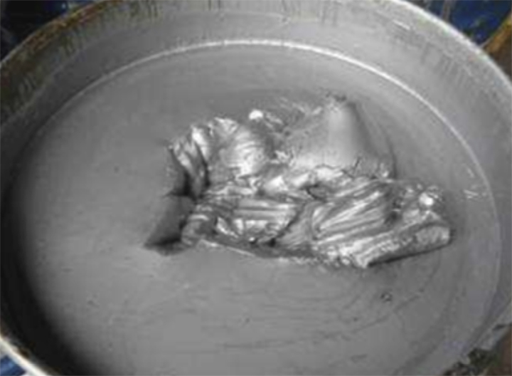
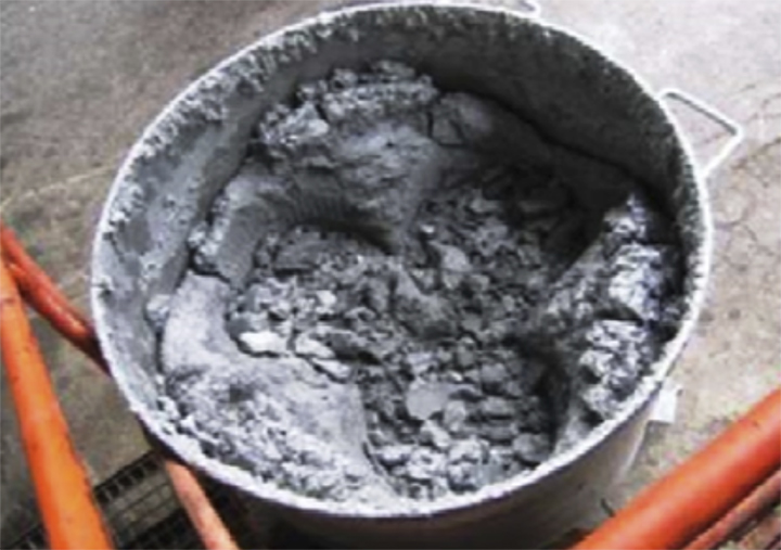
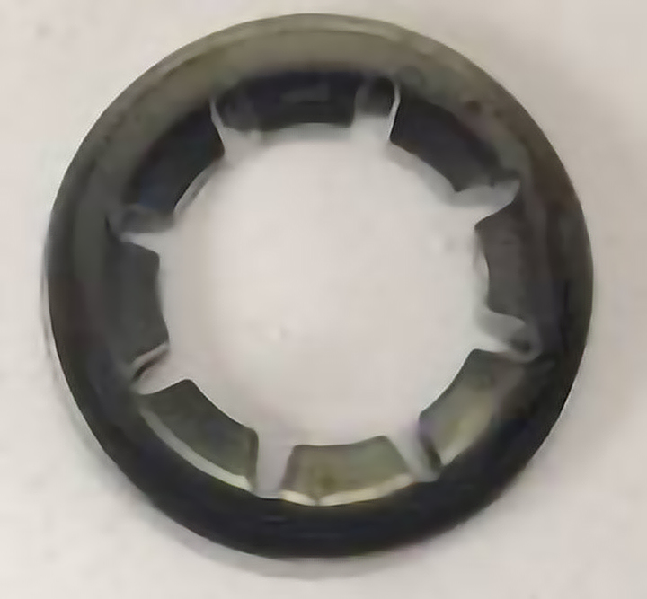
For example, if the air temperature is 30 °C and relative humidity is 55%, moisture will condense on surfaces at 20 °C or below (see figures 18). Zinc flake basecoats are extremely moisture-sensitive, so the coating temperature must always be at least 3 °C above the dew point. A table for dew point reference is in the appendix. Contact with water irreparably damages the zinc flake coating, causing the binders to react and form a viscous mass that may fully harden (see figures 19 and 20).
The dew point table is found in Appendix Table 11.

There are a number of analytical methods available which may be used to assess the surface properties of the pre-treated articles. As some of the available analytical methods may not be practical to perform due to their cost, the tests described in this section provide simple and economical means of assessing surface properties utilizing reference components for comparative purposes. In all instances, standardized test procedures must be used to assess the properties of the pre-treated articles.
The tests on pre-treated articles described in this section are not intended to be used to qualify a coating system for release to the end customer. As there are many variables associated with the coating process, it is necessary to conduct tests to monitor the quality of the coating system on a regular and defined frequency.
These tests must be introduced, validated, and performed in accordance to the requirements of the quality management system. Each lot must be checked according to statistical guidelines.
The copper sulfate test can be used to check the cleanliness of the surface of the pre-treated metal substrate. When applied to a bare steel surface, copper sulfate solution produces a visible chemical reaction (e.g. adherent copper precipitation) which only occurs when the substrate is free of residues such as oil, grease or scale (see also Annex D 'Sealing test – Procedure: Spot test').
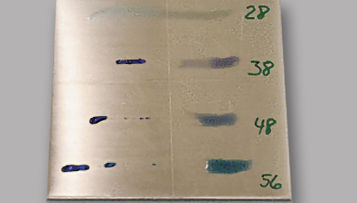
As there is a direct correlation between surface tension and surface cleanliness, surface tension test inks may be used to determine the cleanliness of the pre-treated substrate. For example, substrates which have a higher surface tension are cleaner than those which have a lower surface tension. To determine the surface tension of the pre-treated substrate, several test inks may be required. By comparison to an internal reference standard, the surface tension measurements may be used to determine if the minimum cleaning requirements for a particular coating process have been fulfilled.
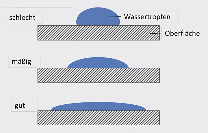
The cleanliness of pre-treated substrates which have been degreased may be checked by applying water droplets to the surface of the parts. If the droplet of water is observed to bead up when applied to the part surface, it can be concluded that oil or grease is still present and the surface is not clean. If the droplet is observed to spread across the part surface, it can be concluded that the surface is clean and free of contamination from oil or grease.
The cleanliness of pre-treated substrates which have been degreased may be checked using a product consisting of small ceramic beads (0.125 mm – 0.250 mm) called Zirblast® B60. To assess surface cleanliness, a pre-treated part is immersed into a container which has been filled with Zirblast® B60. Upon removal from the container, the part is tapped gently against a solid surface two times and then visually examined for presence of adhering Zirblast® B60 residue. If Zirblast® B60 residue is observed on the part surface, it can be concluded that the substrate is not clean (i.e. not OK). If the Zirblast® B60 residue is not observed on the part surface, it can be concluded that the surface is clean (i.e. OK). This test must always be carried out using new (i.e. unused) Zirblast® B60 material.
7.2.2 Corrosion resistance
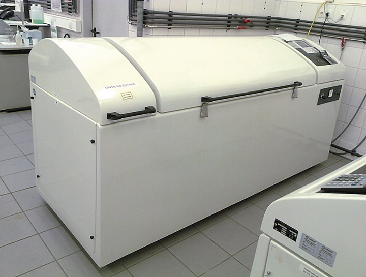
There are a number of methods available to evaluate the corrosion resistance of coated articles. To determine the duration of time required to form white or red corrosion, the salt spray tests according to ISO 9227 and ASTM B117 are the methods that are most commonly used.
The salt spray test is carried out in an atmosphere with specified conditions. As a result, it is necessary to use automatic test equipment. In addition, introducing copper ions into the salt spray test chamber must always be avoided. As a result, components composed of copper or copper alloys should not be tested in the same salt spray chamber as components made of other metals (e.g. steel). A list of suppliers of measuring instruments can be found in Appendix A "Suppliers of supplementary materials and equipment".
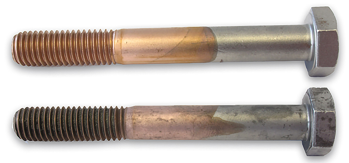
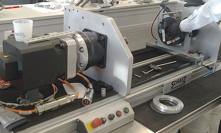
The coefficient of friction has a considerable influence on the assembly of fasteners as it determines how much torque is converted into pre-tensioning force (i.e. the force which holds two components together). If the coefficient of friction is too high, the pre-tensioning force will be reduced and the force holding the components together will be too low to ensure a proper connection. When the coefficient of friction is too low, the opposite effect occurs and the fastener may break due to high pre-tensioning force. The mathematical and testing principles for measuring coefficient of friction are described in ISO 16047. In addition to ISO 16047, there are many customer specific test methods for evaluating coefficient of friction. These test methods require the use of specific reference parts (e.g. nuts, washers, strips) which can lead to differences in coefficient of friction results.
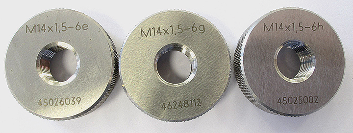
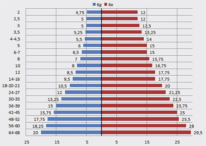
To ensure there is a sufficient amount of space available in the fastener threads to accommodate the coating system, the thickness of the coating materials must be taken into account during fastener thread production and sized in accordance to the corresponding thread tolerance classes. The maximum coating thickness permitted for various fasteners sizes and thread tolerance classes has been calculated and tabulated within ISO 10683 (shown graphically in the Dörken Instruction, see Figure 33). To evaluate fasteners for gauging of threads, test equipment according to ISO 1502 is used. In addition, DIN EN 26157 must also be used to evaluate threads for damage and impact points. As the same test equipment is used to inspect threads for these defects, the error pattern must be checked accurately.
The average weight of the coating can be determined very easily. A suitable number of parts (e.g., 5 screws) are weighed before and after coating. The difference represents the coating weight for the respective number of parts.
Since the parts themselves may have weight variations, it is recommended to mark the parts used for weighing in such a way that they remain identifiable after coating. This ensures that the same parts are weighed and that no error occurs due to variations in the individual part weights. It is advisable to wear gloves during the process.
- Tools: precision scale, gloves
As our products are applied in thin coating layers (i.e. a few μm), the coating thickness measurement requires the use of specialized instrumentation that is properly maintained and calibrated. The three most commonly used methods for measuring the thickness of our coating systems are described in this subsection.
The thickness of individually applied coating layers as well as the total thickness of the complete coating system may be measured with instruments that operate based on the principle of induction. For coating materials applied to steel substrates, the coating thickness is measured with a probe that generates a magnetic field under the coating layer. A probe which generates an eddy current is used to measure the thickness of coating materials applied to other non-ferrous metals (e.g., aluminum, copper). In most cases, the same instrument can be used for both ferrous and non-ferrous substrates, provided the correct probe is selected. With this technique, the measured value depends on the distance between the probe and the substrate (e.g., steel). The measurement reproducibility is approximately 10%.
It is necessary to ensure that the instrument is calibrated for each new part prior to taking coating thickness measurements. If the instrument allows the part calibration to be stored as an application, it is acceptable to use this feature by selecting “Appl No.” The application should be verified before taking coating thickness measurements on the sample parts. To verify the application, take several measurements on the uncoated substrate metal. If the coating thickness value is within the range of 0 (+/- 2 μm), the application may be used to take thickness measurements on the coated samples.
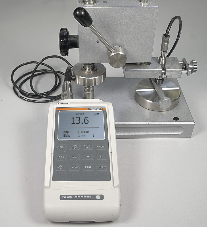
Example procedure: Measuring coating thickness with the Fischer MP40:
- Turn on the instrument power and wait until the display shows “ready for operation” before taking measurements.
- When taking multiple coating thickness measurements of the same sample, ensure the block evaluation begins with n=0. After taking five to ten measurements, press “Block-Res” to obtain statistical results (mean value, STD, etc.). Pressing “Block-Res” again shows the individual readings. Variation in coating thickness of +/- 3 μm is permissible and not a cause for concern.
How do I measure correctly?
- Curved surfaces: Carry out the calibration on the curved surface using a test stand and a probe wedge.
- Small measuring area: For very small parts, calibration and measurement should always be performed at the same location.
- Field penetration depth: Ensure there are no fluctuations in the base material thickness. Perform calibration on the actual measuring area.
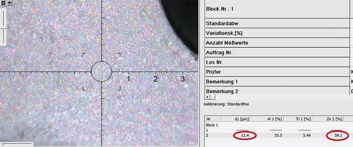
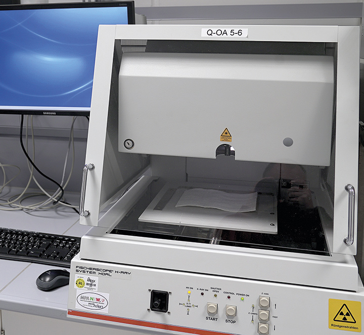
The thickness of the zinc flake basecoat layer may be measured using an X-Ray fluorescence (XRF) spectroscopy instrument. When the XRF method is used, a beam of X-Ray energy is directed onto the surface of the coated part. The beam penetrates the coating and excites the elements in the zinc flake coating, causing them to emit characteristic energy that can be detected. The amount of X-Ray energy absorbed increases as the coating layer becomes thicker. When properly calibrated with appropriate correction factors, the thickness of the zinc flake basecoats can be measured accurately using this method. Correction factors for each zinc flake coating are available upon request from Dörken.
Measurement tips:
- Curved surface: Carry out the calibration on the curved area using a test stand and probe wedge.
- Small measuring area: For very small parts, calibration and measurement should always be performed at the same location.
- Field penetration depth: Ensure there are no fluctuations in base material thickness. Perform calibration on the measured surface.
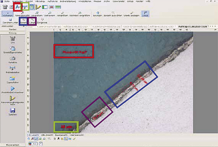
The most precise method for determining the applied coating thickness is the preparation of a cross section with subsequent microscopic evaluation. In the event of a dispute regarding coating thickness, the microscopic method described in ISO 1463 shall be used as the referee testing method.
Adhesion of the coating system to the substrate is usually evaluated by means of an adhesive tape test and it may also be carried out in conjunction with a cross-cut test. When using this method to assess coating adhesion, a strip of adhesive tape is placed firmly on the surface of the sample and smoothed out to remove air pockets using fingers or an eraser. The tape is then rapidly removed at an angle perpendicular to the substrate and visually examined for presence of adhering coating materials. As there are aspects of this test which are difficult to reproduce (e.g., the contact pressure, the speed of tape removal, and the visual evaluation of coating), the same type of adhesive tape should be used when conducting the test.
When the coating adhesion test is conducted on a part that has been coated with a zinc flake basecoat (i.e., no topcoat), it is normal and acceptable to observe slight removal of coating material on the adhesive tape. However, if the amount of coating material removed by the tape also exposes the metal substrate, this is an indicator of poor coating adhesion.
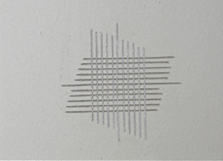
The cross-cut test is conducted by scribing a 6 × 6 lattice pattern (i.e., 25 squares) on the surface of the coated article with a sharp knife. A detailed description of the cross-cut test and the evaluation criteria can be found in ISO 2409.
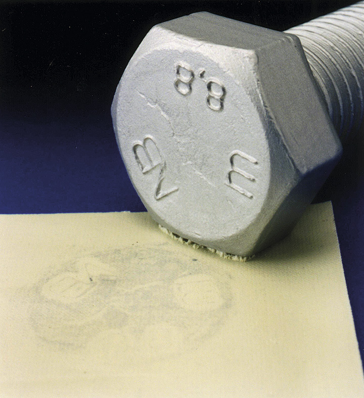
Copper sulfate solution can be used to determine if a topcoat sealer has been applied over electroplated zinc or a zinc flake basecoat. To conduct this test, copper sulfate solution is placed on the surface of the coated article and the visual appearance is observed for changes. If a topcoat has been applied to the part, the color of the copper sulfate solution will remain the same. If the copper sulfate solution becomes brown or black in color within just a few seconds, there is too little or no topcoat present on the surface of the coated part. (See Appendix D “Test for sealing – procedure: spot test”).
Comments (1)
Do you have constructive feedback?
Please log in to leave a comment.